- Familiarization
PenghuiLW High Speed Centrifuge 355 It is mainly used for the treatment of drilling fluid, especially for drying on the solid phase in sensitive areas.
- Use of environmental conditions
Ambient temperature: -20 ° C ~ +50 ° C
Relative humidity of the ambient air: no more than 95%
Explosion-proof class: ExdIIBT4
Corrosive Environment: corrosive gas or vapor without damage to metals and insulation
Electrical protection: IP54
- Structure and principle of operation
1.2.1 Structural composition
This machine is mainly composed of a unit of rotating parts, Power Transmission Systems, Overload protection systems, Basic Hull, supply tube and electrical system.
The diagram of the main unit is shown in the figure 1. Disassembly of the device is shown in the figure 2.
- Rotating Part Assembly
It consists of a drum, Screw Propeller, differential and other components and is supported horizontally by the two main support seats on the base of the. The drum is a column-conical structure, And the inner surface is welded with many ribs along the axial direction. The large end plate of the drum has six rafts, which can adjust the depth of the liquid pool. The screw assembly is assembled with a core, Accelerator, spiral blade, etc. D., And the bearing on two half-vars of both ends is coaxially located in a rotating drum and is connected to the differential through a spline shaft. Pushrod spiral double-headed and left, and the surface of the pusher is treated with wear. A component-by-component image of a rotating part assembly is shown in the figure 3.
- Overload and overload protection system
Transmission
The main drive is controlled by an explosion-proof motor, which is driven by a liquid coupling through five triangular belts and a main pulley to drive the drum. The auxiliary drive is driven by an explosion-proof motor, And the differential input shaft rotates through the differential pulley and the overload protection device through three triangular bands.
Overload Protection Device
Adopt Mechanical Electrical Double Protection Measures. Mechanical protection includes two parts: hydraulic clutch and mechanical torque overload protection device.
- Basic Chassis
Including prefabricated carton, foundation, shock absorber, hanging basket, etc.. D.
- Supply Pipe Assembly
Including Supply Pipe and Clean Water Pipe The pure water pipe is used to clean the centrifuge before stopping.
- Electrical system
Includes control cabinet, Travel switch and corresponding cable.
1.2.2 Principle of operation
- How a centrifuge works
Cm. Drawing 4. When drilling fluid is continuously fed from the supply pipe (1), it enters the drum (7) From the feed port (5), and the drum rotates at high speed, And the screw (4) Acts on the differential (9). Then rotation at speed, a little smaller, than a rotating drum, The rotating drum and screw form the separation transfer mechanism, having a certain rotational speed and high-speed rotation in one direction.
When an annular liquid basin is formed in the drum by a centrifugal force of hundreds or even thousands of times greater, than gravity, Due to the density difference between the solid phase and the liquid phase, heavier solids particles settle on the inner wall of the drum to form a precipitate. Under the relative motion of the spiral blade and the rotating drum, the sediment is pushed to the small end of the rotating drum and discharged from the outlet (12) Slag. Liquid phase, in which the inner ring is lightened, Discharged through a spiral passage through an overflow opening (11), thereby realizing the process of obtaining continuous separation of solid and liquid phases.
- Differential function and working principle
The function of the differential is to create a differential speed between the screw and the drum. The principle of operation is shown in the figure 5. Differential Housing (3) Rotates with centrifuge drum (2) at the same speed, An auxiliary motor drives the input shaft (5) through pulley (4), And the two speeds are combined with the auger by a two-stage planetary gear (1) Difference in rotation speed relative to the drum, That is, the difference in rotation speed.
The formula for calculating differential velocity is as follows:
△n = (nR-nG) / ir / min
Where nR: Speed of differential input shaft r / min;
nG: Drum Speed R / min;
i: differential velocity coefficient;
Δn: Differential speed. When the value of "-", the auger lags behind the drum, when the value of "+", The auger moves forward over the drum. This car belongs to the first.
- Working Principle and Principle of Fluid Coupling
Pulley lubrication connection, used in this machine, is a hydraulic connection, torque limiting, and the structure is shown in the figure 7. Pump impeller (15) Directly connected to the motor shaft, and the power is transmitted through the hydraulic medium through the turbine (6) – Pulley connected to it (4) – triangular tape – The driving main pulley controls the rotating drum. Since the power is transferred to the turbine through the liquid medium, which is spiral in circumference between the turbine (6) and pump impeller (15), The direct load start condition of the electric motor is changed to the start of the flexible load, so that the load starts smoothly and splits. Impact function. The clutch is a static pressure clutch during unloading. When the load increases and the turbine speed decreases, The rotation speed of the liquid in the side auxiliary chamber is also reduced, Static head is reduced, and the fluid in the working chamber is partially inflow into the lateral auxiliary cavity, so that the clutch capacity can be reduced, and the moment is limited. On the other hand, due to significant changes, When the centrifuge is overloaded during the production process, The difference between the rotational speed of the pump wheel and the turbine increases, which leads to an increase in the operating temperature of the oil inside the fluid coupling. If the overload time is long and the operating temperature of the oil rises to 125 ° C, Fusible Plug (11) on the clutch body melts, working oil is sprayed, clutch idling, has no power output, The engine is unloaded, thereby protecting the centrifugal role of the machine.
- Overload Protection Device Function and Working Principle
Torque overload protection device mounted at the end of the differential, As shown in the picture 8. Power Transmission Screw (7), bead (6) to transmit force, corps (5) Torque, Disc Spring (10), dial (4) and so on. D. The dial is connected to the differential input shaft (12) with the help of a safety pin (11). There is also a bracket at the left end of the torque housing, established on the basis of (6), a roller of the upper end of the bracket (6) is in contact with the torque housing.
When the centrifuge is overloaded or the screw accidentally gets stuck, Steel Ball (6) on the torque case is released from the power transmission hole on the dial (4) under the influence of the overload force and slides to the lowest position of the dial. At this time, the corps (5) torque is moved to the left by a disc spring (10), and transfer screw (7) Detaches, And the differential pulley is idling, thereby protecting the differential and screw. At the same time, by pressing the stroke switch roller (Fig.6), The electrical control system works, power is turned off, and the whole machine stops.
- Advantages of the equipment
1 The main part of the drum is made of hot forged material UNSS32304. It is tested by non-destructive testing, And its mechanical properties and tensile strength are superior in the same industry.
2 All bearings adopt high-quality SKFFAG series bearings, that have a longer lifespan, than in the same industry.
3 The wear-resistant wear-resistant hose is made of YG6S material with super abrasive material, which has high impact strength and wear resistance and will not break easily.
4 Main components of the drum, after three dynamic balancing procedures, Dynamic Balance Average Speed 1300 about / min, The actual dynamic balance of operating speed and full balance of maneuvers ensure uninterrupted operation of the centrifuge during high-speed operation.
5 The surface of the screw is spray-welded with THW super abrasive for easy maintenance and longer service life.
6 Adopt mechanical and electronic controls of two-layer safety action, Hydraulic clutch and mechanical torque overload protection device.
7 The double-layer labyrinth of the centrifugation design effectively solves the problem of fluid flow into the bearing housing during the operation of the equipment.
8 Centrifugal Bearing Housing Design of Oil Drain Device, So that excess lubricating oil can be removed into the bearing housing cavity in time, Taking away heat energy, generated during high-speed operation, which can effectively reduce the temperature of the bearing and improve the service life of the bearing.
- Common errors and troubleshooting
| Number | Defect | Reason | Fault Exclusion Method | Prophylaxis |
| 1 | The engine does not start | 1. Power supply not supplied; 2. The torque of the torque overload device is not reset; 3. Control cabinet components are damaged. |
1. Make sure, that the travel switch is reset first, Then ask a professional electrician to check, Is peripheral power normal; 2. Have a professional electrician check the control cabinet components. |
|
| 2 | Spiral flywheel stuck (Phenomenon: Not a single slag is discharged, The screw cannot rotate relative to the drum, The torque overload device is switched off, The safety pin can be cut, and the travel switch starts.) |
1. If the supply quantity is too high or the solid mud content of the drill hose is too high, the auger is overloaded. After that,, How The Torque Overload Protection Device Is Disabled, The screw cannot discharge the slag, causing dirt and sand to accumulate in the drum and block the spiral; 2. Slag drain port blocked. |
1. Check first, whether the slag drain hole is blocked, and clean the slag drain port if necessary; 2. Replace the safety pin and reset the transfer device; 3. Stop the drum and rotate the differential input pulley back and forth with your hand. At the same time, rinse the water into the drum and drain the sludge. Do not press the one-way actuator, otherwise, the overload protection device may be switched off again. Until then, until the work area is rotated to more than 50 time (when the screw rotates one revolution relative to the rotating drum), can be considered, that the discharge is complete; 4. Start without a load and see for yourself, that the auger is working correctly. |
1. Modify the production process if necessary, to reduce the amount of processing or solids; 2. When starting, the supply valve should open gradually and never open suddenly. |
| 3 | The vibration of the machine is increasing | 1. After the last work, the drum is not completely cleaned, and there is dry sediment in the drum; 2. Bearing wear; 3. Dynamic balance is destroyed; 4. The damper does not work; 5. When starting or stopping near a critical speed point, moderate vibrations occur. |
1. Check, whether the auger is stuck, if it is already blocked, Process it according to fault two; 2. If the screw motor is not stuck, First, check the correctness and consistency of the sponge node, Regardless of, whether the wear sleeve is damaged, whether the main bearing is damaged (Rotating drum, Check, whether the bearing rotation is blocked), Connecting screw Does it come off, etc.. D. After a normal inspection, the drum is washed again with clean water, And the screw turns to discharge the sludge. Boot won't start, Make sure, that the error has been resolved; 4. Replace the damper if necessary; 5. Vibration at the critical velocity point does not require treatment. |
1. The drum must be thoroughly cleaned after each work. In winter, the water in the drum must be completely emptied through the drain hole, to avoid freezing. 2. Run the machine strictly according to specifications and adjust the fascia at the same time; 3. Lubricate the bearings according to regulations and constantly monitor the temperature rise of the bearing housing. |
| 4 | Alloy swimming trunks | The direct reason is that, that the clutch is overloaded and the oil temperature is rising. Cause of overload, Usually, consists in, that the feed quantity is too high or the solid content of the drilling fluid is too high, Slag outlet blocked, Main bearing damaged, and the working oil is too much or too little. | 1Address the first fault, Fault Two, to check the cause of the congestion, and process accordingly; 2. Check the amount of oil in the clutch; 3. Replace the fuse plug. |
1. Always monitor the increase in the temperature of the coupling, Usually, the normal operating temperature is less than 90 ° C; 2. Lubricate the bearings according to regulations and constantly monitor the temperature rise of the bearing housing; 3. Change the production process if necessary, to reduce the amount of processing or solids. |
| 5 | Differential sound is abnormal | 1. Incorrect amount of oil or oil; 2. Differential wear; 3. Differential bearing damaged. |
As soon as the differential sound turns out to be abnormal, Stop it immediately and inform a professional mechanic. Or replace a new differential. | Check and replace differential lubrication regularly, to choose the right oil. |
| 6 | Solid Phase Discharge: Little or Not | 1. A wiring error results in the wrong direction of rotation; 2. Drive belt slippage or clutch oil is insufficient, which leads to insufficient drum speed; 3. The physical properties of the drilling fluid are not suitable; 4. The spiral propeller blades are badly worn; |
1. A wiring error results in the wrong direction of rotation; 2. Drive belt slippage or clutch oil is insufficient, which leads to insufficient drum speed; 3. The physical properties of the drilling fluid are not suitable; 4. The spiral propeller blades are badly worn;… |
1. Regularly check the tightness of the tape and the oil level of the hitch; 2. Connect the motor cable correctly; 3. Develop the right technical solution for drilling fluid treatment. |
- Technical Parameters
| Model | LW355*1257-N | LW355*1257BP-N | ||
| Drum Inner Diameter(mm) | 355 | 355 | ||
| Drum Working Length(mm) | 1257 | 1257 | ||
| Maximum drum speed rpm | 3400 | |||
| RPM Drum Speed | 2800 | 3000 | ≤3200 | |
| Particle size of separation μm | 2-5 | |||
| Dimensions, mm | 3000*1500*1990 | |||
| Processing power (unit weight<1.1)m3/h | 22-30 | 0-36 | ||
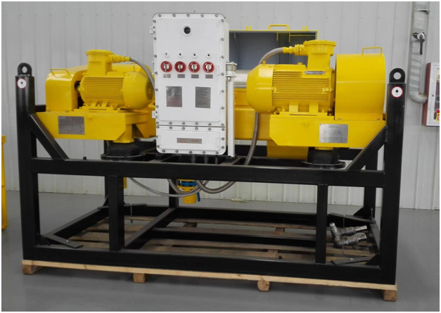
- Equipment Photos

Centrifuge


